






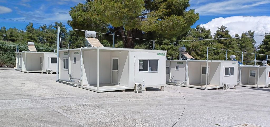
Heating Systems That Increase Energy Efficiency in Container Houses
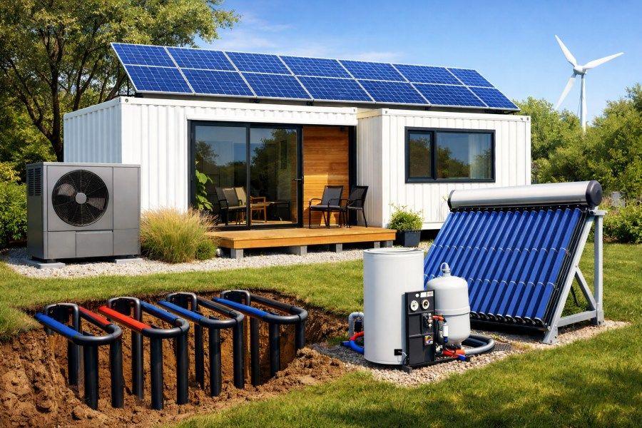
Improving energy efficiency in container homes doesn’t just mean lower bills; it means a more balanced living space, sustainable comfort year-round, and a long-lasting structural system. Because these lightweight metal-framed structures conduct heat quickly, using smart solutions that minimize heat loss is vital. Therefore, today’s container home owners are trying to improve their quality of life with various technologies, from heat pumps and radiant heating systems to solar energy and smart thermostats.
Choosing the right heating system provides a long-term investment advantage for the user. Energy-efficient systems both regulate the temperature of the house and reduce maintenance costs by ensuring less strain on appliances. In other words, these systems are planned not only for today but also for the future. In this article, we examine all the heating technologies that can improve the energy performance of your container home step by step, detail their advantages, and explain which user profiles they are suitable for.
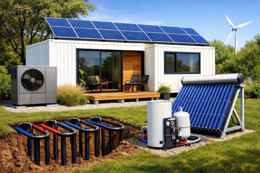
The Importance of Energy Efficiency and the Role of Heat Management in Container Homes
Energy efficiency is a much more critical issue in container homes compared to reinforced concrete structures. This is because container structures are made of metal surfaces, and these surfaces transmit outside heat very quickly. If proper heat management is not provided, an uncomfortable interior becomes excessively hot in summer and quickly cold in winter. This situation both reduces the quality of life and puts the user in an economic bind due to high energy consumption. However, these problems can be easily managed with advanced heating systems and insulation reinforcements.
Thermal management isn’t just a technical matter; it’s a comfort factor that affects daily life. If your home is still warm when you wake up in the morning, if you don’t experience temperature fluctuations throughout the day, and if appliances don’t have to constantly run at full power, then you live in a home with proper thermal management. Therefore, energy efficiency depends not only on the power consumption of appliances but also on the system’s compatibility with the home and its optimization according to user habits.
Choosing the Right Insulation and System to Reduce Heat Loss
The main sources of heat loss are wall joints, floor and ceiling panel lines, and door and window leaks. Reinforcing these areas with the right materials ensures that the heating system operates much more efficiently. A heat pump used in a container house with reinforced insulation can provide a stable temperature without consuming excessive electricity. This both extends the life of the device and provides economic benefits to the user.
Choosing the right heating system is equally important. Using high-capacity appliances for small container homes will only create unnecessary energy consumption. Similarly, choosing an underpowered system will not heat the house sufficiently and will cause the appliances to run continuously. Therefore, determining the correct appliance capacity is the first step towards efficiency.
Smart Heat Management Approaches That Enhance User Comfort
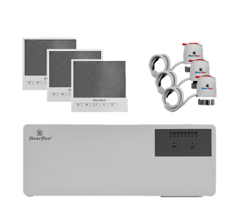
Smart thermostats and sensors are modern solutions that prioritize user comfort. These systems can lower the temperature when you’re away from home and raise it back to the ideal level before you return. This saves energy and ensures the user always enters a space at the ideal temperature. This automation offers a significant advantage, especially for busy professionals.
Sensor technologies also prevent energy waste. For example, features such as the device automatically shutting off when a window is open, operating in low mode overnight, or gradually reducing the heat when it detects prolonged inactivity naturally decrease energy consumption. We have panels that are compatible with smart home application modules in this regard.
High-efficiency heating and cooling with electric, gas-fired, and heat pump systems.
Container Home Architecture: Suitable Assembly and Capacity Selection
When choosing a heating system, the square footage of the house, panel thickness, and insulation quality must be taken into account. Installing a large-capacity system in a container house is energy-wasteful. Instead, a professional capacity analysis ensures the device performs correctly. This can be calculated based on the container’s heat loss.
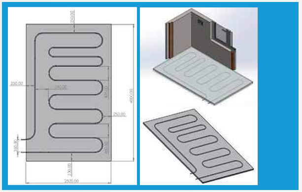
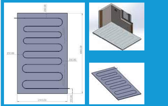
- Floor Area: 10 m² | Pipe Length: 24 m | Distance between pipes: 400 mm | Hose length per square meter: 2.4 m
- Floor Area: 10 m² | Pipe Length: 22 m | Distance between pipes: 400 mm | Hose length per square meter: 2.2 m
- Floor Area: 10 m² | Pipe Length: 26 m | Distance between pipes: 300 mm | Hose length per square meter: 2.6 m
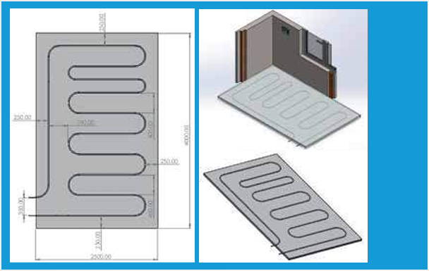
These are example calculations and estimated applications. ( This varies depending on the characteristics of the windows and building elements. When considering panel heating, heating and cooling can be achieved from both the walls and ceiling.)
Calculation programs and application methods are determined according to living space comfort.
We have specially designed calculation programs.
Our calculation scenario;
First, to give a precise figure, we must know the temperature difference between the indoor and outdoor environments ($\Delta T$). Heat loss is directly proportional to the temperature difference. Therefore, we can proceed with two different scenarios for heat loss calculations: winter conditions (the most critical case) and current summer conditions.
1. Calculation Based on Winter Conditions (Heating Period)
Average temperatures in Athens during the winter months range between 7°C and 15°C. In January, the coldest month, the average low temperature is around 7°C, while the average high temperature is around 14°C.
Let’s assume the container temperature is +22°C.
For the worst-case scenario, $\Delta T = 22 – 7 = 15°C$
If the floor area is 10 m² (the wall area will be recalculated)
base dimensions of 2m × 5m (perimeter = 14m):
Wall area = 14 × 2.5 = 35 m²
$Q = 0.53 \times 35 \times 15 = 278.25$ Watts ( 0.278 kWh per hour )
2. Calculation Based on Summer Conditions (Cooling Period)
Today in Athens, the air temperature is between 25°C and 33°C. Assuming the container is at +22°C (air-conditioned), there is a heat gain because the outside is warmer than the inside. In this case:
$\Delta T = 33 – 22 = 11°C$ (for the warmest hour)
$Q = 0.53 \times 35 \times 11 = 204.05$ Watts (heat gain)
Notes:
- These calculations are for polyurethane panel walls only ; floors, ceilings, doors and windows, and air leaks are not included.
- The actual total heat loss may be 30-50% higher than these values.
Summary Table
| Scenario | Wall Area | $\Delta T$ | Heat Loss / Gain | The actual total heat loss is 50%. |
|---|---|---|---|---|
| Winter (7°C outside, 22°C inside) | 35 m² | 15°C | 278.25 W (loss) | 417.38 W (loss) |
| Summer (outside 33°C, inside 22°C) | 35 m² | 11°C | 204.05 W (gain) | 306.08 W (gain) |
Basic Assumptions and Data
- Container Dimensions: In the previous calculation, we used a base area of 10 m² and a height of 2.5 m. Accordingly, the total wall area was calculated as 35 m².
- Heat Loads (From Previous Calculation):
- Winter (Heating Requirement): Assuming an outside temperature of 7°C and an inside temperature of 22°C, the heat loss was 278.25 W.
- Summer (Cooling Requirement): Assuming an outside temperature of 33°C and an inside temperature of 22°C, the heat gain was 204.05 W.
- Pipe Specifications: A pipe with a thermal conductivity coefficient ($\lambda$) of 0.42 W/mK will be used.
- Water Temperatures: Use water at a maximum temperature of 50°C for heating and a minimum temperature of 10°C for cooling.
Calculating the Required Pipe Length
To find the required pipe length ($L$) for heating or cooling, we use the basic heat transfer formula. The key factor here is the temperature difference between the pipe and the ground ($\Delta T$).
Formula:
$Q = \lambda \times L \times \Delta T$
If we rearrange this formula for pipe length:
$L = Q / (\lambda \times \Delta T)$
Here:
- $Q$ : Heating or cooling requirement (in Watts).
- $\lambda$ : Heat transfer coefficient of the pipe (0.42 W/mK).
- $\Delta T$ : The average temperature difference between the water in the pipe and the ground (or environment).
Required Pipe Length for Winter (Heating):
- Heat Demand ($Q$): 278.25 W
- Temperature Difference ($\Delta T$): Here we must assume an average floor temperature. A comfortable floor temperature for underfloor heating is approximately 29°C. Therefore, $\Delta T = 50°C$ (water) – $29°C$ (floor) = $21°C$.
Let’s calculate:
$L$ (heating) = $278.25$ W / $(0.42 \text{ W/mK} \times 21°C)$
$L$ (heating) = $278.25 / 8.82$
$L$ (heating) $\approx 31.5$ meters
Required Pipe Length for Summer (Cooling):
- Cooling Requirement ($Q$): 204.05 W
- Temperature Difference ($\Delta T$): Ideally, the ground temperature for cooling should be approximately 20°C (above the dew point temperature to prevent condensation). Therefore, $\Delta T = 20°C$ (ground) – $10°C$ (water) = $10°C$.
Let’s calculate:
$L$ (cooling) = $204.05$ W / $(0.42 \text{ W/mK} \times 10°C)$
$L$ (cooling) = $204.05 / 4.2$
$L$ (cooling) $\approx 48.6$ meters
3. Conclusion and Evaluation
| APPLICATION | Required Pipe Length |
|---|---|
| Winter (Heating) | Approximately 32 meters |
| Summer (Cooling) | Approximately 49 meters |
Important Notes:
- This calculation is a theoretical and simplified approach. In a real project, it is affected by many factors such as pipe length, spacing (usually 10-20 cm), thermal conductivity of the floor covering, pipe diameter, and water flow rate. ( Container lining is suitable because of its high thermal conductivity and supports heating and cooling.)
- For example, a common practical approach in the industry uses an average of 3-5 meters of pipe per 1 m². Based on this rough calculation, 30-50 meters of pipe is recommended for a 10 m² area. This is close to our theoretical calculations and represents a safer approach.
- Considering that temperatures in Athens can reach 38°C in the summer, the cooling need may increase even further, which could necessitate extending the pipe length.
4. INSULATION
In underfloor heating systems, floor insulation is as critical as (or even more critical than) the heating itself. This importance increases exponentially, especially if you are using a steel container like yours.
Heat always flows from hot to cold. With underfloor heating, the 50°C water in your pipes won’t just heat the air above as you’d like; if there’s no insulation underneath, a large portion of the heat will escape directly down to the floor (soil or concrete).
- Specifically for your container: Your walls have a U-value of 0.53 W/m²K (quite good). However, if the floor is only made of 2-3 mm thick steel sheet, its U-value is approximately 5-6 W/m²K (almost 10 times worse).
- Numerical Comparison: Let’s say you have a 10 m² floor area. You haven’t installed any insulation on the floor, and the outside temperature (or subsurface temperature) is 7°C (Athenian winter). The average temperature difference between 50°C water and the floor is approximately 35°C.
- Loss without insulation: $Q = U(5) \times A(10) \times \Delta T(35) = 1750$ Watt (This is 6 times the 278 Watt you lose through all your walls!)
- With 5 cm of polyurethane insulation ($U \approx 0.44$): $Q = 0.44 \times 10 \times 35 = 154$ Watts (Your energy loss is reduced tenfold).
In other words, without insulation, 70-80% of the energy from the hot water you produce would be used to heat the ground instead of heating the room.
Thermal Comfort and Surface Temperature Equality (Hot-Cold Spots)
delivers the greatest promise of underfloor heating: “even and gentle warmth under your feet.”
- Without insulation, enormous temperature differences will develop between the area where the pipe passes and the spaces between the pipes. The top of the pipeline will be hot, while the spaces between the pipes will be cold.
- Insulation cuts off the heat you generate from below in a “layer,” ensuring that the entire floor surface heats evenly (e.g., 29°C). This maintains thermal comfort (ASHRAE standards).
System Response Time (Heating and Cooling Rate)
Insulation reduces the inertia (lack of resilience) of the heating system.
- Without insulation: To prevent heat from escaping, the pipes first need to heat that massive layer of concrete and the soil beneath it. It could take hours for your container to heat up.
- If insulation is in place: The heat you produce remains almost entirely within the screed layer and the room. The system responds much faster (heats up in 30-45 minutes). This is a great advantage, especially in regions with temperature fluctuations throughout the day, such as Athens; it heats up quickly in the cool morning and cools down quickly in the warm afternoon (the same principle applies in cooling mode).
Condensation and Humidity (Especially for Cooling)
This is perhaps one of the most critical points. You are planning to cool the area with 10°C water.
- If there is no subfloor insulation, the ground surface where the cold pipes are located becomes very cold. In the Athenian summer, when the humid outside air enters the container, it condenses (sweats) on this cold surface, reaching the dew point. This leads to the floor becoming slippery, mold growth, and rust.
Good floor insulation (which acts as a vapor barrier) prevents condensation by keeping the floor surface temperature above the ambient dew point. (Therefore, 10°C water is too cold in cooling mode; 16-18°C is generally recommended, the floor will definitely sweat at 10°C without insulation).

IT IS A CRITICAL STEP IN THE ASSEMBLY PROCESS IN TERMS OF EFFICIENCY .
The application can be done not only on the floor but also on the side walls. Heat movement homogenizes the environment.
ADVANTAGES FOR THE PRACTITIONER
- Less Piping: Due to its high heat transfer capacity, it can be laid over wider distances.
- Easy Shaping: More flexible structure, unaffected by air temperature.
- Easy Transport: The products are much easier to transport and store compared to their counterparts.
- Thin Structure: Application in a thickness of 4-5 cm.
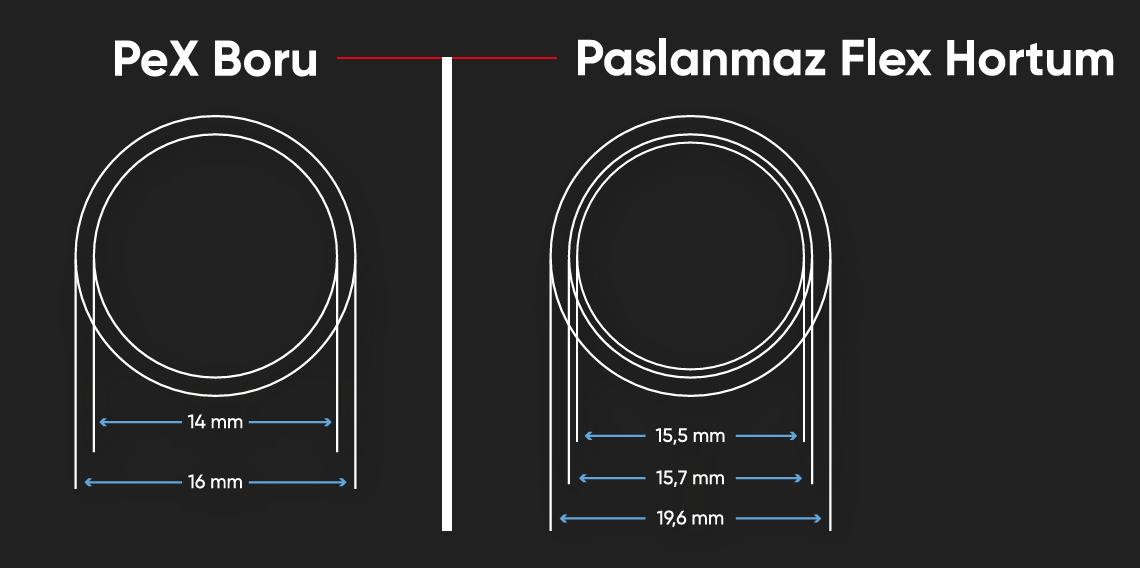
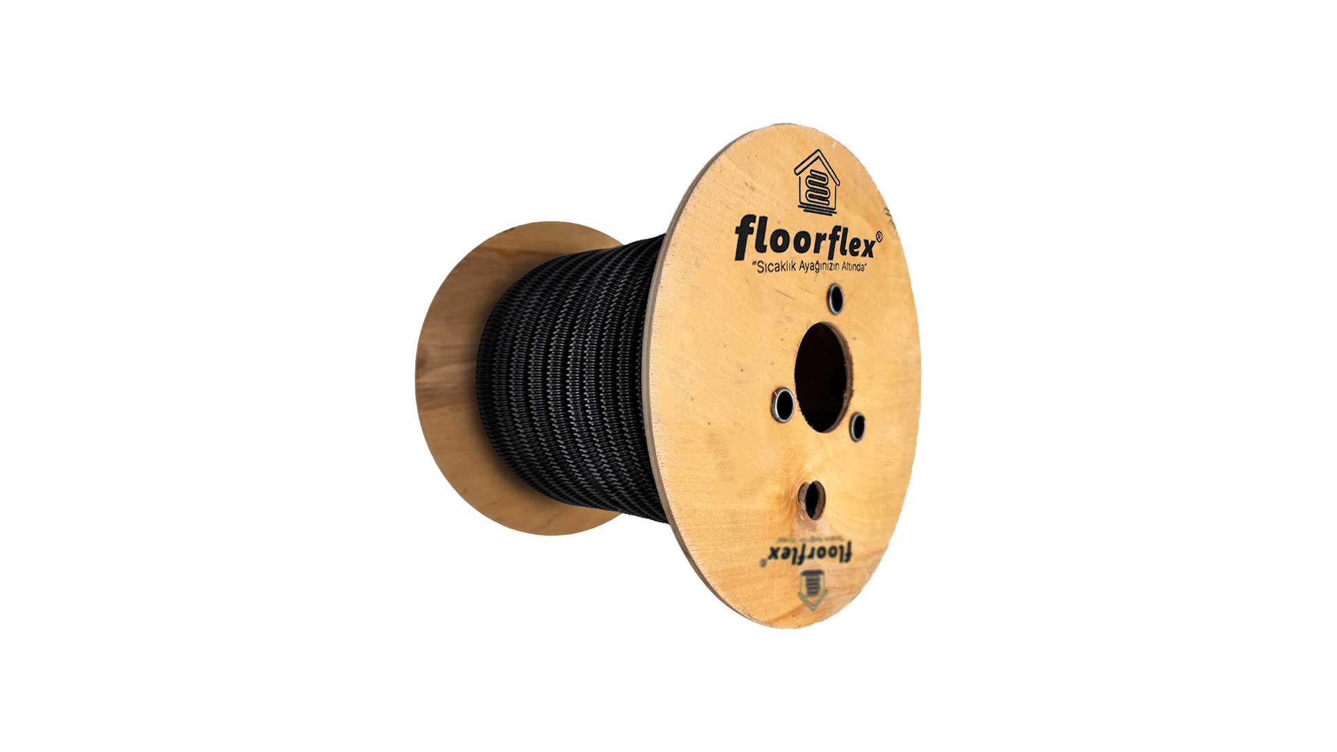
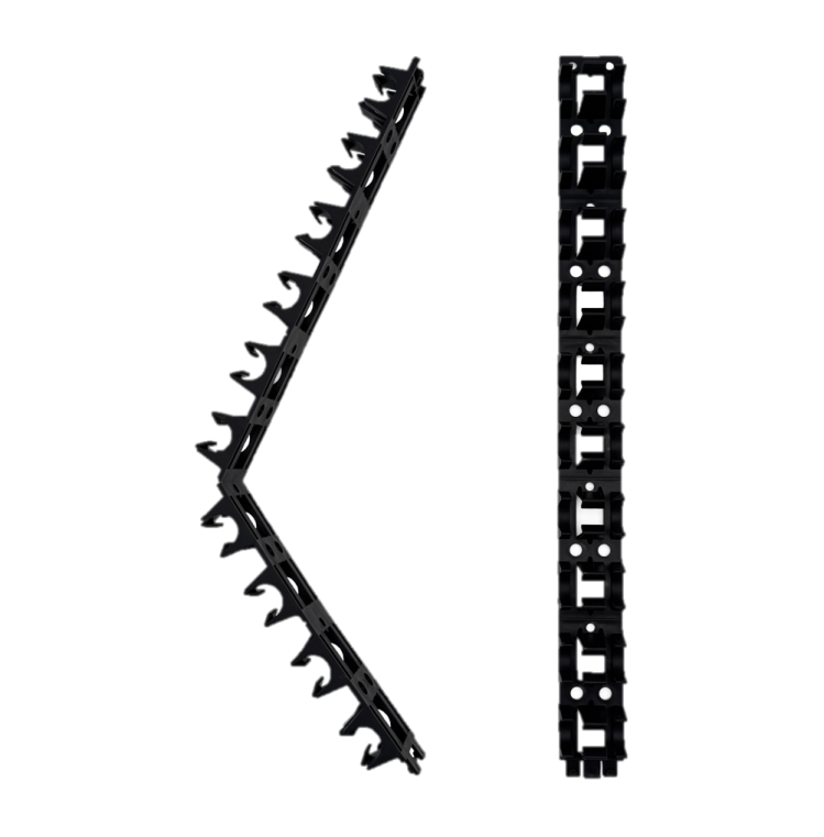
FLOORFLEX HOSE CLAMP
Fastening elements can be fixed to the container surface area or body profiles with screws.
Size = DN15
Materials
Main Material = PE
Application and Features: Used for securing FloorFlex stainless steel hoses.
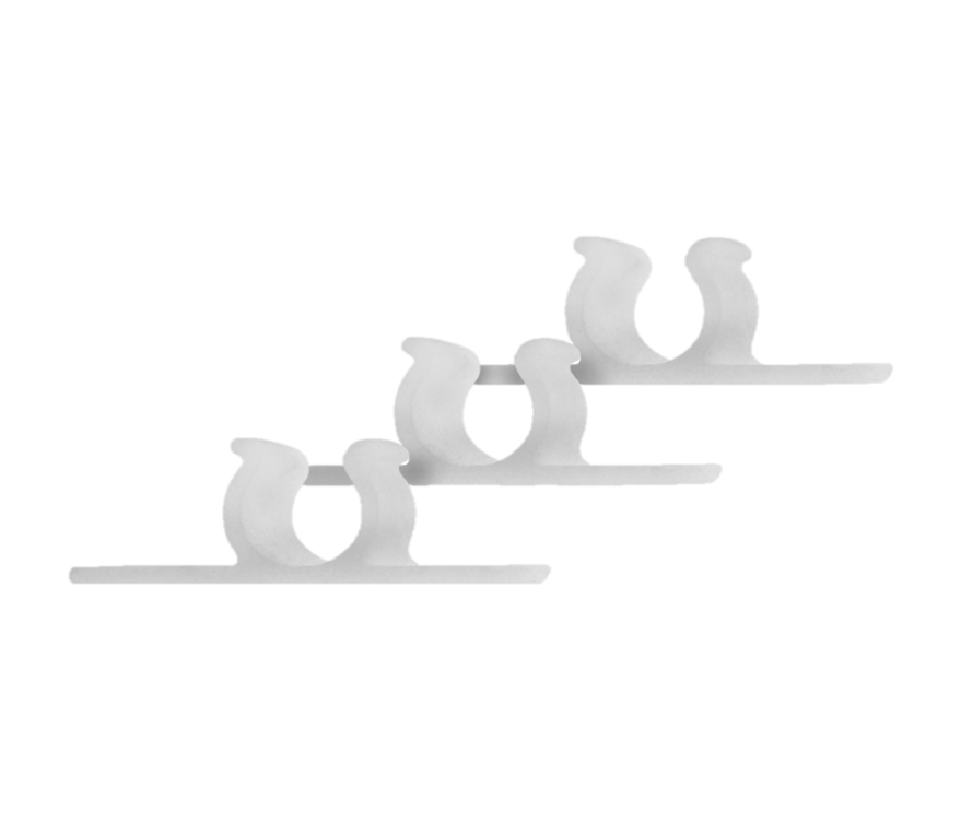
FLOORFLEX REFERENCE CLAMP
Dimensions = DN15 Length 50cm
Thickness = 5mm
Materials
Main Material = PE
Areas of Use and Features
FloorFlex is used to secure stainless steel hoses to surfaces. It is 50cm long and features clamps spaced 5cm apart, allowing for easy adjustment of hose spacing during installation and resulting in a more organized system. It can be used in entire installations, or in sections where other fastening elements are used, to create a more organized system.
All these details directly affect the device’s efficiency and longevity.
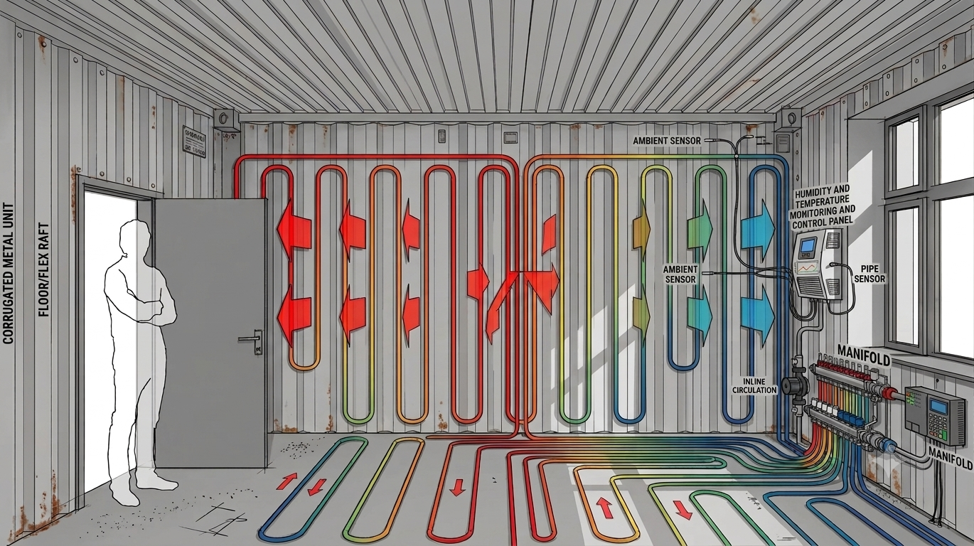
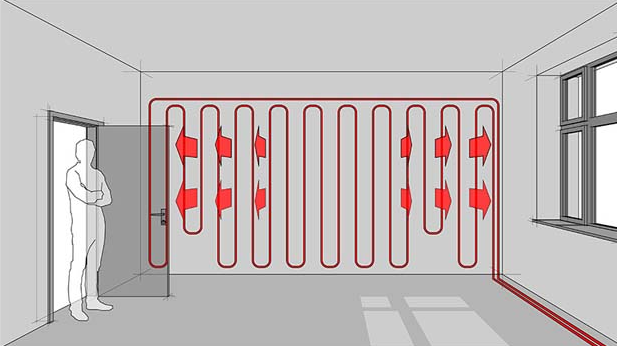
Clarifications Regarding to Wall Implementation of Floorflex UFH System
In wall panel heating and cooling systems, panel height has two different meanings. Here are the details you should pay attention to, depending on your preference:
1. Net Thickness Covered Inside the Wall:
The total system thickness, where the water or electrical pipe system is mounted to the wall and covered with plaster/ drywall , is generally kept between 3 cm and 5 cm .
Water-based systems: The polystyrene/panel thickness and pipe diameter average 17 mm , and a 2 cm thick structure is obtained with the applied coating . The coating material must be a heat-conducting material. There should be a minimum air gap between the pipe and the coating.
2. Active Panel (Pipe) Height on the Wall Surface:
Standard starting and ending heights of the active system to be installed on the wall surface, according to the needs of the room to be heated/cooled:
Ground Start: Heating systems are started 10-15 cm above the ground.
Ceiling Finish: Depending on the room’s intended use (e.g., to prevent furniture or cabinets from being hidden behind the ceiling), the active floor height is typically finished at 2.00 – 2.20 m . In full-height applications, attention is paid to window/cabinet alignments.
** The calculations were made based on the heat transfer coefficient given to us. So we assume that there is minium 5 cm polyurethane or similar isolation on walls and floor too.
** Unless the steel profile frame is in contact with the ufh piping structure, an extra insulation mat is not needed. The structural element ( the container’s isolated wall panels) itself performs its insulation function.
** Calculations were made based on the heat loss and gain of the structural elements. The company can perform its own engineering calculations in this regard. It has been observed on their website that they produce containers in different structural forms.
Important Tips:
Cooling Restriction: When operating in cooling mode , the room temperature and dew point must be monitored to prevent the risk of condensation (sweating).
Risk of Damage: To mitigate the risk of drilling or hammering nails for tasks such as hanging pictures on the wall, a detailed pipe layout (x-ray) of the panels must be recorded.
ATTENTION: COMBINED APPLICATION OF UNDERFLOOR HEATING AND UNDERFLOOR COOLING SYSTEMS
Underfloor cooling systems use the same layouts as underfloor heating systems. The installed system can be used for both underfloor heating and cooling in the space. Thus, a significant portion of both heating and cooling needs can be met with a single system, significantly reducing the load on air-based systems that provide heat transfer by convection. This means smaller air handling units and lower initial investment costs. In a system that will operate as both an underfloor heating and cooling system, attention should be paid to ensuring that the thermal resistance of the floor covering is low. Special additives should be used for the screed. By thinning the screed thickness, a more easily controllable system should be created. In this way, the highest possible cooling capacity can be achieved without causing condensation . Pipe spacing and pipe diameter should be determined according to the cooling needs of the space . By keeping $\Delta T$ lower, heat distribution in the floor should be more uniform. In addition, pressure loss can be reduced by preferring shorter lines and/or larger diameter pipes. Condensation is another issue that should be considered during the design of underfloor cooling systems . Condensation occurs when the temperature of the cooling surface falls below the dew point temperature. Below this temperature, the air cannot retain moisture and turns into liquid. When the cooling surface remains below the dew point temperature, condensation occurs on the surface.
What is the dew point? The dew point is a function of dry-bulb and wet-bulb temperatures. Wet-bulb temperature is determined by relative humidity. As relative humidity increases, wet-bulb temperature also increases. Consequently, the dew point decreases. The dew point can be determined using a psychrometric table. Therefore, meteorological data of the province where the design is being carried out should first be examined, and the feedwater temperature should be determined accordingly.
CONDENSATION PROTECTION
Underfloor cooling systems can react quickly to sudden increases in humidity. The control strategy for all radiant cooling (floor, ceiling, and wall cooling) should focus on altering the fluid temperature rather than cutting off the fluid supply. In underfloor cooling systems, this strategy should be implemented to provide condensation protection against various temperature changes.
CONTROL SYSTEMS
Due to sudden increases in humidity and potential climate changes, control systems that monitor the temperature or flow of the feedwater must be installed. To obtain the highest efficiency from the cooling system, the control devices must receive data from humidity sensors . Using a standard room thermostat instead of a humidity sensor increases the risk of condensation and prevents the cooling system from operating at full capacity.
AI- powered application diagram has been drawn.